
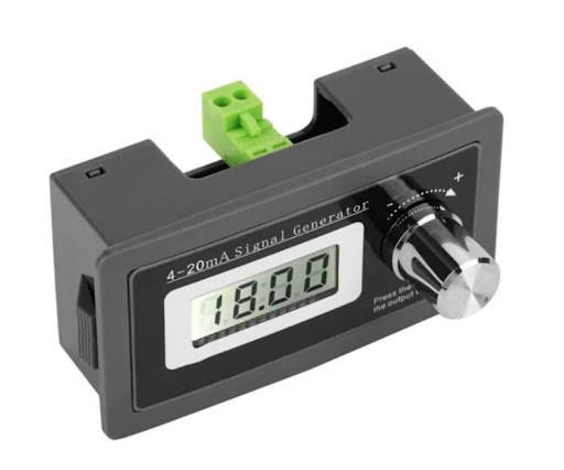
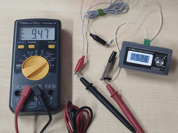
In part 1 we will already explain what 4-20mA signal and Technical specification and their applications. Now we are going with other features of a 4-20mA signal generator.
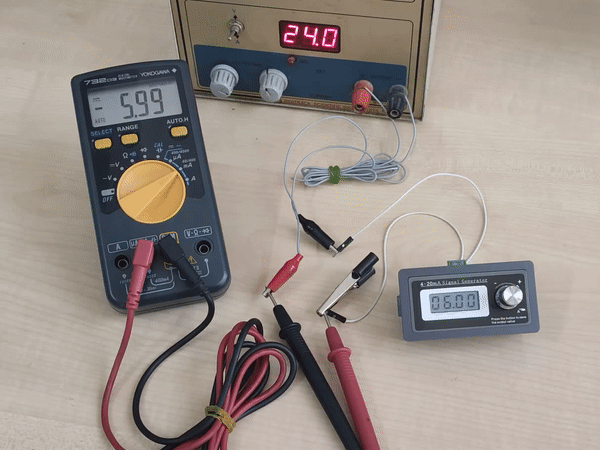
How to set Fine and Coarse Adjustments?
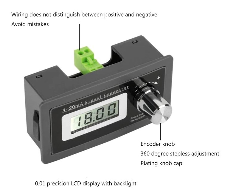
The Coarse Adjustment means it covers the Entire range from minimum to maximum, In contrast, the fine adjustment only covers a fraction of the entire range. For Fine-tuning and Coarse-tuning, Rotate the Knob clockwise for “+”, and Anticlockwise for “-” Press and hold the Knob for 2 seconds to enter the parameter setting mode.
Coarse Adjustment:
- To enter the Coarse tuning parameter setting press and hold the Knob for 2 seconds, and enter the password “+–+”
- Now when we enter the F001 Mode rotate the Knob to set the Mode in “0” mode
- Next rotate the Knob in clockwise to enter to that F004 Mde
- This F004 Mode have coarse tuning setting from 1-50 digits
- If we set the coarse tuning value 10, then current varies from 10mA to 11mA, similar for other ranges(1-50)
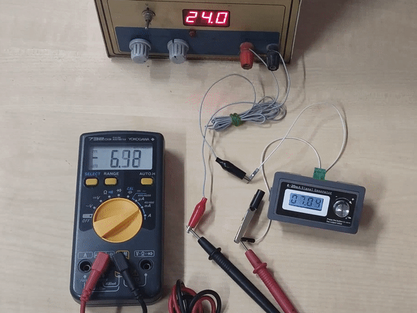
Fine Adjustment:
- To enter the Coarse tuning parameter setting press and hold the Knob for 2 seconds, and enter the password “+–+”
- Now when we enter the F001 Mode rotate the Knob to set the Mode in “1” mode by rotating the Knob.
- Next rotate the Knob in clockwise to enter to that F005 Mde
- This F004 Mode have coarse tuning setting from 1-50 digits
- If we set the coarse tuning value 10, then current varies from 10.08mA to 10.18mA, similar for other ranges(1-50)
Check out our website www.probots.co.in to find all the parts for your projects! We have 2000+ Electronic Modules, Sensors, and Components for all your electronics projects.

You can purchase this signal generator here – Buy Now
How to generate Curve Waves?
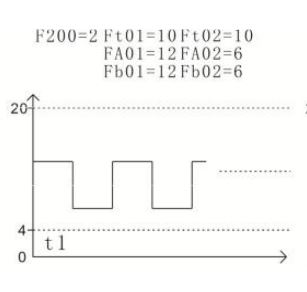
To generate the Curve waves from the signal generator, you need to enter the F200 mode.
Entering the F200(Curve Output Setting) required password is “-+-+”.
| Index | Designation | Comments | Default |
| F200 | No. of Curves | 0: Not Used 1-9: Segment number | 0 |
| Ft01 | Section 1 Run Time | 0-999 sec. Must be“F200”>0 | |
| FA01 | Section 1 Start current | 3.00-21.00mA | |
| Fb01 | Section 1 End current | 3.00-21.00mA | |
| Ft02 | Section 2 Run time | 0-999 sec | |
| … | … | … | |
| Fb09 | Section 9 End current | 3.00-21.00mA |
- In this Each curve has 3 parameter,
- Section 1 Run time (Ft01) is 0-999sec
- Section 1 Start Current Time (FA01) is 4-20mA
- Section 1 End Current Time (Fb01) is 4-20mA
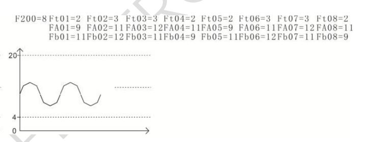
Examples of Automatic Curve Output setting;
Generating Ramp wave
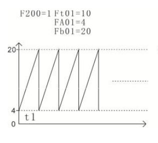
For generating the curve, we need to enter F200 Mode, by entering the password ”-+-+”.then and F200 is value should be greater than 0. follow the below steps.
- Ft01 means run time for the curve. By varying the Ft01 value to set the running time of the curve.
- FA01 means start current value of the curve(4-20ma).
- FB01 means end current value of curve.
- Similarly for all curves we need the following settings.
Generating Square wave
Generating Sine wave
All the components used in this article are readily available on our website. And also other interesting electronic components are there, Please visit https://www.probots.co.in/robots.co.in, and also you can place it online, we can deliver it. images only for reference