
This is a two-part article that explains the step-by-step details of interfacing USB to RS485 Converters to Communicate with Modbus Devices. The first part explains the procedure to read and transmit RS485 data from using the converter and the second part of the article explains how to communicate with MODBUS devices.
All the modules that you require to implement this project are available on our website. Visit: Probots
What is a Modbus?
Modbus is a data communication protocol originally published by Modicon (now Schneider Electric) in 1979 for use with its programmable logic controllers(PLCs). Modbus has become a de facto standard communication protocol and is now a commonly available means of connecting industrial electronic devices for data transmission.
The Microcontroller cannot communicate with the Modbus directly, that is why we use an rs485 converter. With this, the microcontroller can communicate with the Modbus. An important point to pay attention to is that Modbus is not a hardware protocol but a software protocol.
In this article, we will use the USB to RS485 Converter to receive RS485 data. We will program the Arduino to transmit data and read it using the USB to Serial Converter.
The Arduino will need a library called SoftwareSerial.h which can be found online.
Driver Installations:
The USB to Serial converters show up as a COM Serial Port when plugged into the computer. You will have to install the appropriate drivers before you use them. To install the drivers on Windows, open Device Manager and identify the USB to Serial Converter Chip used in your converter. It is usually CH340, FT232, CP210x, etc. Each of these chips has different drivers. You can get the latest version for free download online.
Refer to this article for driver installation for CH340 – Sparkfun
Components Required:
- Arduino Uno
- MAX-485 TTL to RS-485 Converter Module
- USB to RS485 Converter Module Adapter Board
- Bread Board
- Jumper wires
Circuit Connections between MAX-485 TTL to RS-485 converter module and Arduino UNO:
| Arduino UNO | MAX-485 TTL to RS-485 Converter Module |
| 10 | RO |
| 11 | DI |
| 4 | DE & RE |
| +5V | VCC |
| GND | GND |
Circuit Connection between MAX-485 TTL to RS-485 Module and USB to RS-485 converter:
| MAX-485 TTL to RS-485 Converter Module | USB to RS-485 Module Connected with PC |
| A | A |
| B | B |

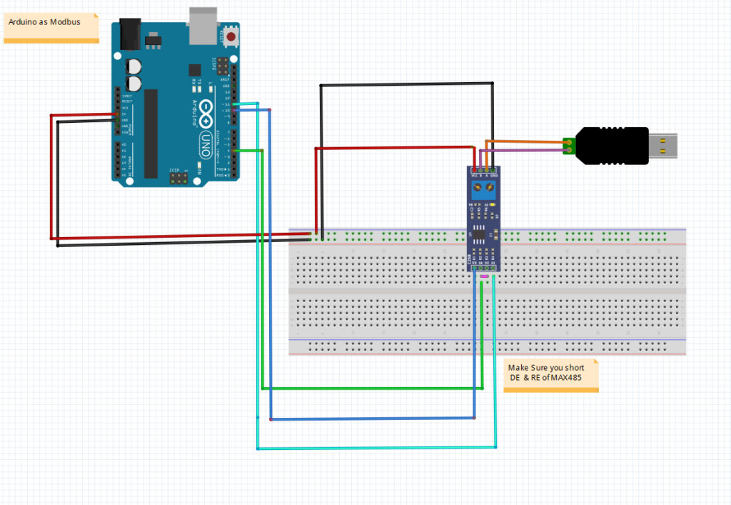
We are using the software serial port on the Arduino as the hardware serial port is being used for programming the Arduino through USB.
The advantage of using this library is software serial allows you to open another serial port on the Arduino, so there will two serial ports were sending and receiving data to the computer. This allows the Arduino to communicate with the RS485 and the Computer simultaneously.
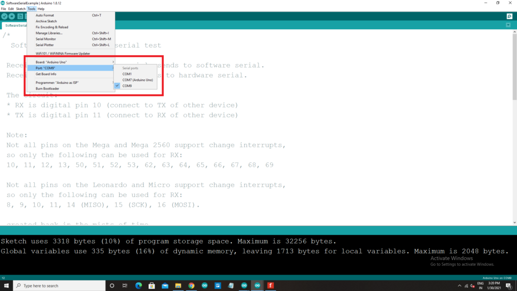
- Once the connections are made, select the com port of your Arduino on the Arduino IDE. The Com Port of Arduino and USB RS-485 will be different, so while Selecting make sure you select the right port
- Here we will be using the Arduino to send the data to the converter and in-turn to the USB to rs485, so select the Arduino’s com port.


- Now open the COM port with the appropriate baud rate given in the program, the default baud rate given in the program is 57600 for Arduino, and for rs 485 converter baud rate is 4800 (baud rate can be changed according to users wish)
- In the next step open another window of Arduino IDE and select the com port of the USB to rs485 converter If your converter does not show up as a different COM Port, then check your driver installation.
- Now we can observe, if you type any data or information on the Arduino Com port and click on enter, that data will be transmitted to the com port of USB to rs485 converter. The results are shown in the pics below.
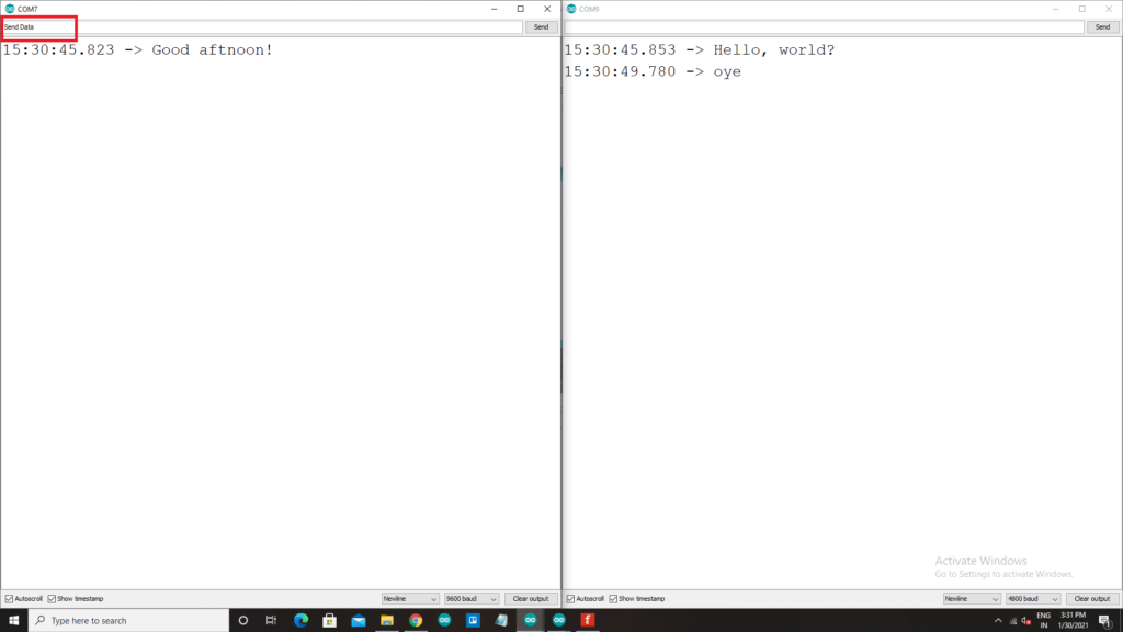
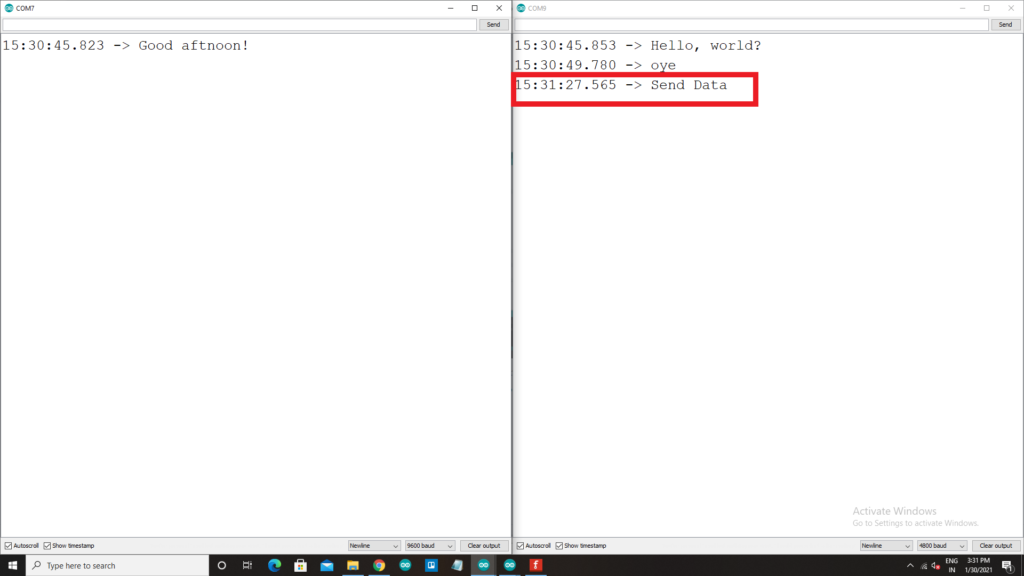
- With this technique, we can make sure that the hardware and the connections made are perfectly working.
All the components used in this article are readily available on our website. Please visit: PROBOTS to buy any components you need to kickstart your project.