In the last part of this article, we explained how to use the MAX30102 Pulse Oximeter Sensor with the Arduino. You can read it here. In this article, we continue from the previous article and how to improve the readings to get stable readings from the sensor.

How to get accurate readings from MAX30102?
The MAX30102 sensor needs to be calibrated with the right settings to get accurate readings from the sensor. Though not medical grade, the MAX30102 sensor can give accurate spo2 readings for most applications.

If you have executed the example program in the SparkfunMAX3010x library and found that the readings are fluctuating, not accurate, or invalid, you can use this article to understand how to calibrate your setup to get accurate readings.
Once you have a working setup ready, you may proceed with the following steps to improve the accuracy –
1.Get a Good Enclosure to mount the sensor to a fingertip
2.Use the Right Settings and Calibration in the Code
3.Using Maxim SPO2 Calculation Algorithm
How to Mount the Sensor to a Fingertip?
The mounting determines the sensor performance more than anything else. It is very difficult to get good readings by pressing and holding the sensor in between your fingers.
You will need an external mechanism that holds the sensor to the fingertip with constant pressure.

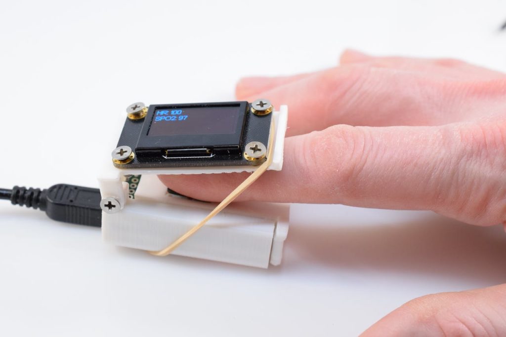
We found using generic rubber bands works well. It holds the sensor with constant pressure over the finger. The algorithm works well in this condition.
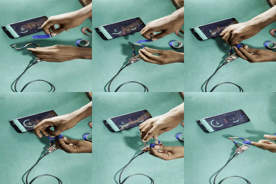
The sensor is very sensitive to ambient light so you have to shield it 100%. We got even better results by using electrical tape and wrapping it around the finger.

How to modify the code to get good readings?
The Sparkfun library program we used in the previous article has a few configurable parameters –
byte ledBrightness = 60; //Options: 0=Off to 255=50mA
byte sampleAverage = 4; //Options: 1, 2, 4, 8, 16, 32
byte ledMode = 2; //Options: 1 = Red only, 2 = Red + IR, 3 = Red + IR + Green
byte sampleRate = 100; //Options: 50, 100, 200, 400, 800, 1000, 1600, 3200
int pulseWidth = 411; //Options: 69, 118, 215, 411
int adcRange = 4096; //Options: 2048, 4096, 8192, 16384
The perfect values for each of these parameters vary for each different sensor mounting mechanism and application. The default values in Sparkfun’s example are a very good starting point. You can start tuning them as per the below table.
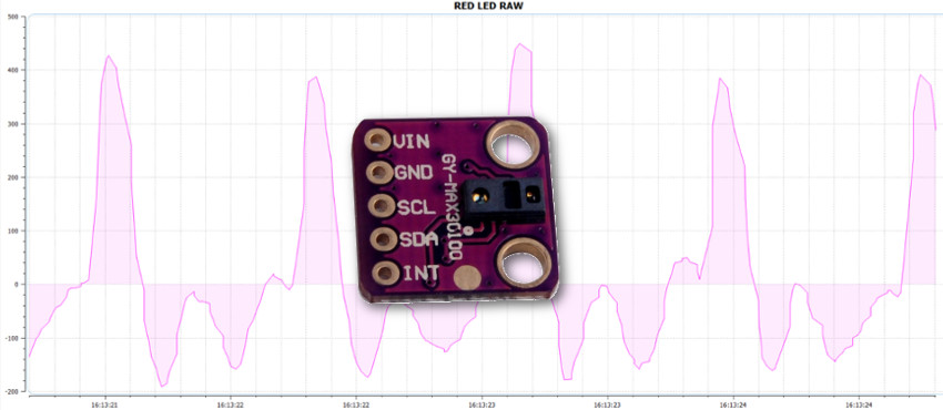
| ADC Range | The sensor transmits red and ir light and measures the reflected light using an ADC. This parameter sets the ADC Range. Start with 2048 during calibration and move higher as required. You can view the Raw IR And RED Light values. The Signals should not be saturated. Pulses should be visible and within 1% of Full Scale |
| LED Brightness | Determines the intensity of both Red and IR Light. Lower the brightness to conserve power in battery applications. Increase the brightness to get good SNR. |
| PulseWidth | Sets the on time for the RED and IR Light. Lower pulse widths with a low sample rate are preferable but the noise will be high. |
| Sample Average | Sets the Sampling rate for internal ADC. You will have to change this to get smooth readings from the ADC |
| LED Mode | MAX30102 supports only Red + IR |
| SampleRate | ADC Sampling rate. Increase/Decrease as per LED Brightness, ADC Range, and PulseWidth. |
You can change these parameters till you get a good satisfactory reading from the sensor. Making one change at a time and observing the raw Red and IR Values will get you closer to the right setting slowly.
Note: The MAX30102 datasheet explains these parameters in detail. Another App Note from Maxim – “Recommended Configurations and Operating Profiles for MAX30101/MAX30102 EV Kits” explains this process in detail. Make sure you read and understand them thoroughly before modifying these parameters.
Scope for Improvement in the Library
Maxim has given out the algorithm and code to convert the values from this sensor to actual SPO2 and BPM values. Sparkfun has done a really great job to convert it to Arduino and give it out as a library.
But Maxim and Sparkun have written the code to be compatible with Arduino UNO which has limited memory and computational power. They use a sp02 algorithm that makes use of a lookup table to calculate the SP02 based on the raw sensor values. I used an ESP32 and changed the sp02 calculation in sp02_algorithm.CPP(find this file in the Sparkfun Library) to –
n_spo2_calc =103.0-(17.0*n_ratio_average/100.0);
This gave me more accurate values and also lets me calibrate the sensor by changing the values of the constants in the equation.
What Next?
The final setup before you start using your oximeter is to calibrate it. Get a medical-grade oximeter that is already calibrated, and compare its readings to your oximeter and modify the above equation accordingly. Refer to this Maxim App Note – “GUIDELINES FOR SPO2 MEASUREMENT USING THE MAXIM® MAX32664 SENSOR HUB”
Hello, thank you for the great article. I’m using max30102 for my final year project but i just need the raw data of LED IR and red. Could you give some suggestions to get good raw data reading from this sensor? Could i use your setting like adc setting sampling rate setting to get more acurate and good raw reading? Thank you in advance.
Hello, thank you for the great article. I’m using max30102 for my final year project but i just need the raw data of LED IR and red. Could you give some suggestions to get good raw data reading from this sensor? Could i use your setting like adc setting sampling rate setting to get more acurate and good raw reading? Thank you in advance
You can use my settings as a starting point. To get the best result, understand how the settings affect the sensor readings and calibrate them to work for your setup.
Hello, thank you for the great article. I’m using max30102 for my final year project but i just need the raw data of LED IR and red. Could you give some suggestions to get good raw data reading from this sensor? What should i do to get more acurate and good raw reading? Could i use your setting suggestion in this article? Thank you in advance.
Check the Sparkfun Example Code.
hello,
As part of my dissertation I have undertaken to design a tele-monitoring system for the health of the elderly that will monitor basic biomedical parameters. I have already purchased the MAX30102 module in order to take measurements about heart Rate and SP02 levels. I mentioned that the readings are fluctuating, not accurate and I try to change the code library like you mention above. But the readings continue to be not accurate . Can you help me to calibrate this sensor ??
If you know and you can , it will be very useful to tell me about modifying the parameters in the code and which the best trade off- tuning
Thank you very much in advance.