
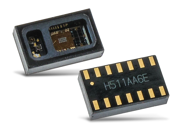
Maxim produces great healthcare sensor ICs. For measuring oxygen saturation and heart rate, they make the simple to use and hugely popular MAX30102 sensor IC. The sensor requires minimal external circuits, provides an interface through I2C, and is almost plug and play! This sensor is a perfect solution for Wearable Devices, Fitness Assistant Devices, Smartphones, Tablets, etc requiring heart monitoring.
In this series of articles, I will detail my experience of working with the MAX30102 pulse oximeter sensor and how you can get it working consistently and use it in a commercial product.
How to get started with the MAX30102 Sensor?
Now, not only does Maxim manufacture an awesome sensor, but they also give detailed documentation on designing the hardware, code, and sensor housing details. All required documents can be downloaded from the Maxim website.
They have an official development board to evaluate the sensor and integrate it into your product. This is the preferred way to start development with these sensors. We didn’t have access to their kits so used third-party hardware to evaluate the sensor.
How to test the Hardware?
If you are getting an official Maxim kit, then you can follow their detailed instructions to start using the sensor.
If you are using a third-party module, then use this article to get the sensor working.
There are many poorly designed third party breakout boards for the MAX30102 sensor available in the market. Majority of the board do not work. The major problem seems to be the logic level voltage on the SCL and SDA lines. The first step is to verify that you dont have a defective board –
| Sensor Pins | Voltage |
|---|---|
| V+ led (Pin ) | Should be less than 6V and capable of supplying upto 200mA |
| Vdd (Pin ) | Operating Voltage for the inbuilt electronics. Should be1.8V. |
| SCL (Pin), SDA (Pin), Int (Pin) | Communication Pins between the sensor and microcontroller. Should be pulled up to vdd or 1.8V. Most low cost boards have a pullup voltage of 2.8V or 3.3V. Make sure the voltage on these lines do not exceed Vdd. |
Note: The above pins refer to the actual pins on the MAX30102 Sensor IC
Make sure the voltage levels on your module satisfies the above specs using a multimeter. There is no point going ahead with a sensor with a poorly designed circuit as you will face problems during programming and usage.
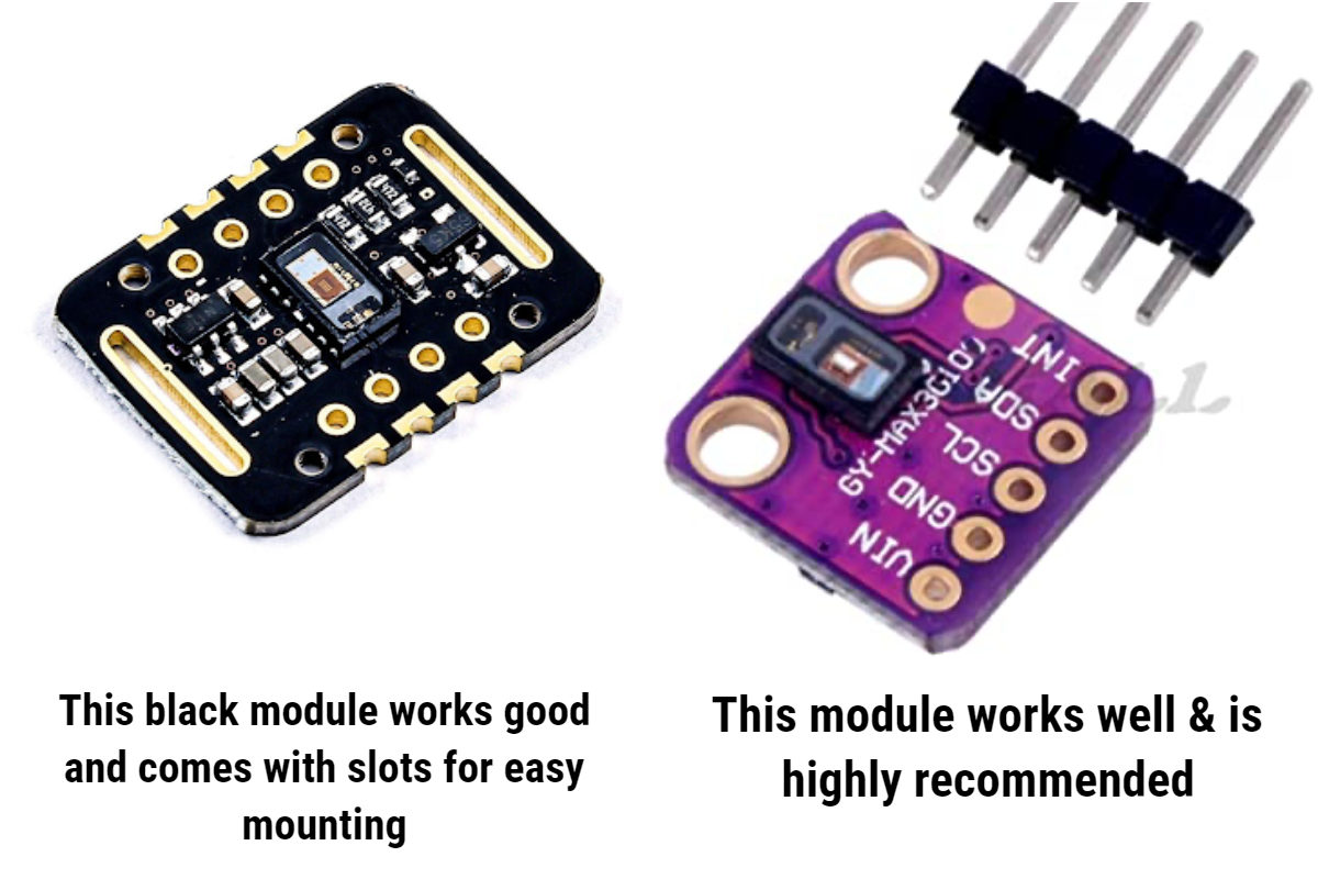
We tested numerous sensor models available and most are poorly designed from unknown suppliers. We couldn’t get them working consistently. The above two modules work well. The sensor on the right is highly recommended and used in this article. It gives the best performance and comes with the right voltage regulators and circuits. The sensor is soldered separately on one side of the board and all other electronics/components on the other side. This makes it easy for placing the module on the fingertip and for designing enclosures. Other sensors are too many components and signals passing around when you press the sensor against your finger.
How to connect the MAX30102 to Arduino?
Any Arduino board having I2C can work with the MAX30102 sensor – UNO, Nano, etc. The MAX30102 sensor gives only raw readings of the sensor.
The microcontroller has to run algorithms to convert these raw readings to actual SPO2 and Heart Rate. Unfortunately, these algorithms require lots of processing and memory power. Maxim has demonstrated its algorithm on an Arduino UNO. But I chose to use a NodeMCU ESP32 as it not only has sufficient processing and memory power but also lets me transmit data over wifi/Bluetooth for quick displaying.
The connections are pretty simple and straightforward –
| ESP32 | MAX30102 Sensor Module |
|---|---|
| 3V3 | VIN |
| GND | GND |
| SDA (GPIO21) | SDA |
| SCL (GPIO22) | SCL |
How to program the MAX30102 using Arduino?
Maxim gives out the code to use it with Arduino UNO. Sparkfun has done a super great job of including all this code as a library that is compatible with the Arduino. You can download it here – Sparkfun Library and also install it within the Arduino IDE
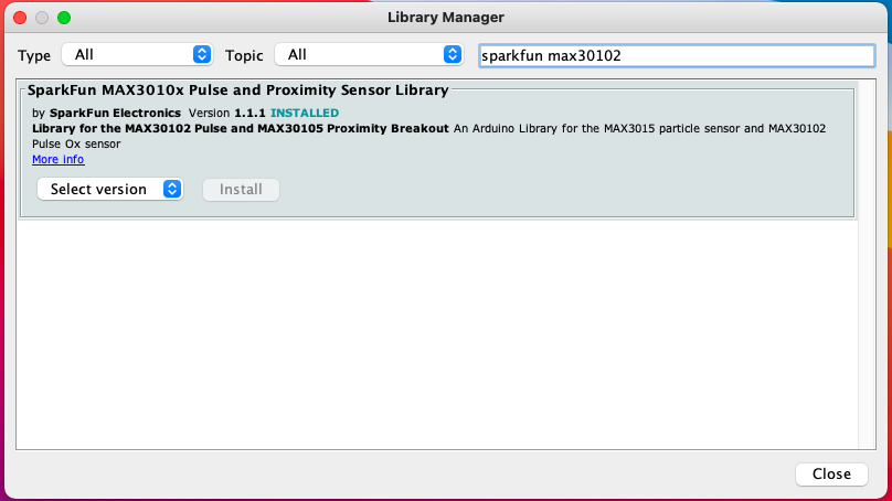
Install the library under Sketch-> Include Libraries-> Manage Libraries under the Arduino IDE
Once you download it you can run and execute the sample programs. The sample programs work great as is with no modification. Just upload the program, hold the sensor on your fingertip and you can start seeing sp02 and BPM Readings on the Serial Monitor.
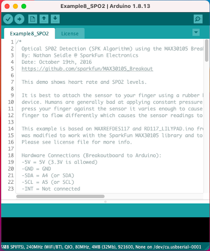
Example8_SPO2 is good to evaluate the sensor. Find it here Files->Examples->Sparkfun MAX3010x Pulse and Proximity Sensor Library
Once the example program is upload, you can open the serial monitor and start viewing the SPO2 and BPM values.
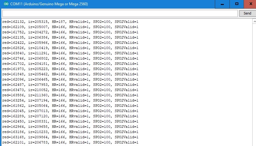
Note: You have to hold the sensor against the sensor with constant pressure for up to 5-10seconds to get a reading. Readings are averaged and take time to stabilize.
If you are getting inconsistent readings and values are constantly fluctuating, you can continue reading Part 2 of this article which explains How to get better readings with the sensor and to tune it to your setup.
Troubleshooting
If you get this error – “MAX30105 was not found. Please check wiring/power.” on the serial monitor then your Arduino is unable to communicate with the MAX30102 sensor.
To solve this first, check voltages on the MAX30102 module and make sure you don’t have a defective module. Then run I2C Scanner. If the I2C Scanner does not detect any devices, then the connections between the sensor and Arduino are wrong. Get your sensor detected by I2CScanner before going ahead with the sample programs.