
Modbus is a data communication protocol originally published by Modicon (now Schneider Electric) in 1979 for use with its programmable logic controllers(PLCs). Modbus has become a de facto standard communication protocol and is now a commonly available means of connecting industrial electronic devices for data transmission. An important point to pay attention to is that Modbus is not a hardware protocol but a software protocol.
All the modules that you require to implement this project are available on our website. Visit Probots
In the RS-485 Modbus network, there is one Master and 127 Slaves each with a unique address from 1 to 127. In this article, we will use Arduino Uno as both Master and Slave for serial communication.
Modbus is mostly used in PLCs (Programmable Logic Controllers). And apart from this, the Modbus is also used in Healthcare, Transportation, Home Automation, etc. Modbus has 255 function codes and there are mainly three popular versions of Modbus:
- MODBUS RTU
- MODBUS ASCII
- MODBUS/TCP
What is the difference between Modbus ASCII and Modbus RTU?
Modbus RTU and Modbus ASCII talk the same protocol. The only difference is that the bytes being transmitted over the wire are presented as binary with Modbus RTU and as readable ASCII with Modbus ASCII. Modbus RTU will be used in this tutorial.
In this article, we will use Arduino as Slave, but before that, to clear the ambiguity we will check the hardware connections to see if the basic communication is happening between the devices. This will delete the thought of hardware issues. Down the lane of this article, we will be dealing with both hardware and software, so if any errors occur we will know the origin of the problem and can be easily solved.
What is RS-485 Serial Protocol ?
RS-485 is an asynchronous serial communication protocol that doesn’t require a clock. It uses a technique called the differential signal to transfer binary data from one device to another.
So what is this differential signal transfer method?

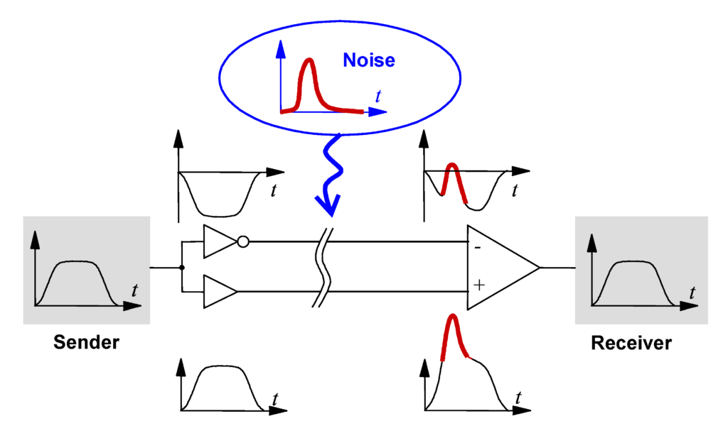
The differential signal method works by creating a differential voltage by using a positive and negative 5V(Eliminates Noise). It provides a Half-Duplex communication when using two wires and Full-Duplex requires 4 fours wires.
By using this method:
- RS-485 supports a higher data transfer rate of 30Mbps maximum.
- It also provides maximum data transfer distance compared to the RS-232 Protocol. It transfers data up to 1200-meter maximum.
- The main advantage of RS-485 over RS-232 is the multiple slaves with a single Master while RS-232 supports only a single slave.
- Can have a maximum of 32 devices connected to RS-485 protocol.
- Another advantage of the RS-485 is immune to noise as they use the differential signal method to transfer.
- RS-485 is faster compared to the I2C protocol.
Now let us divine deep into the article,
Connecting RS-485 with Arduino
RS-485 Modules can be interfaced to any microcontroller having a serial port. For communicating with RS-485 modules with microcontrollers, a module called 5V MAX485 TTL to RS485 which is based on Maxim MAX485 IC is needed as it allows serial communication over a long distance of 1200 meters. It is bidirectional and half-duplex and has a data transfer rate of 2.5 Mbps. This module requires a voltage of 5V. It converts RS485 data to UART serial data which can be directly connected to the microcontroller.

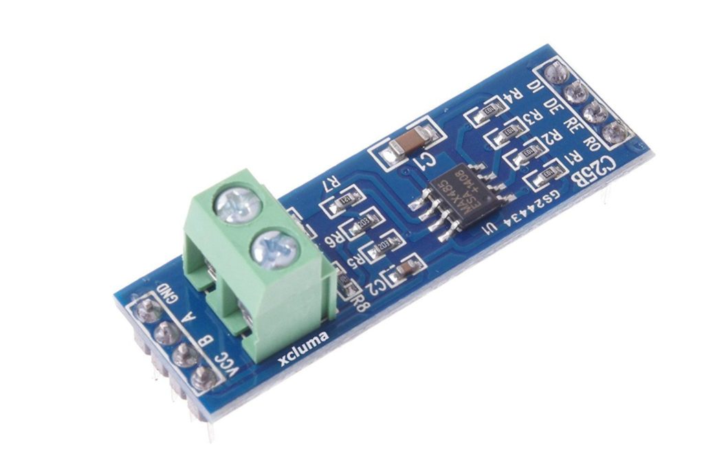
| Pin Name | Pin Description |
| VCC | 5V |
| A | Non-inverting Receiver Input Non-Inverting Driver Output |
| B | Inverting Receiver Input Inverting Driver Output |
| GND | GND (0V) |
| R0 | Receiver Out (RX pin) |
| RE | Receiver Output (LOW-Enable) |
| DE | Driver Output (HIGH-Enable) |
| DI | Driver Input (TX pin) |
USB to RS-485 Converter Module

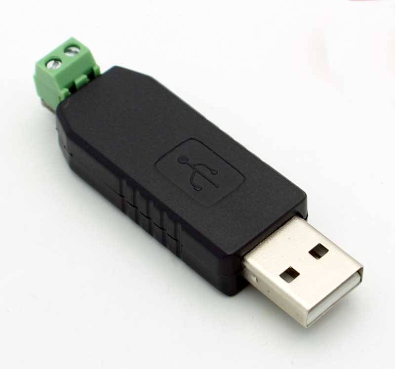
This is a USB to RS485 Converter Adapter module which supports WIN7, XP, Vista, Linux, Mac OS and provides an easy to use RS485 interface by means of using a COM port in the computer. This module is a plug-and-play device. There are no command structures, whatever is sent to the Virtual COM Port is automatically converted to RS485 and vice versa. The module is completely self-powered from the USB bus. So, no need for an external power supply for operation.
It shows up as a Serial/COM port and is accessible from applications or hyper-terminal. This converter provides half-duplex RS-485 communication. The Baud rate range is 75 bps to 115200 bps, maximum up to 6 Mbps.
To use this device there is various Modbus Software available on the internet. In this article, a software called Simply Modbus Software is used.
Simply Modbus Master Software
Modbus Master Software application is needed to send data to slave Modbus RS-485 Arduino devices via COM.
Simply Modbus Master is a data communication test software. You can download the Simply Modbus Master from the given link and learn more about it by referring to Software Manual.
Before using the software, it is important to get familiar with the following terminologies.
Slave ID:
Each slave in a network is assigned a unique unit address from 1 to 127. When the master requests data, the first byte it sends is the Slave address. This way each slave knows after the first byte whether or not to ignore the message.
For us to move further we need to install CH340 Driver please refer the part 1 of this article to get a detailed idea of the driver installations
Hardware Required:
Software Required
Now before entering into the software section, as discussed we will check the hardware working to eliminate hardware errors.
There is already a standalone tutorial written ,which will guide you to eliminate the chances of hardware issues.
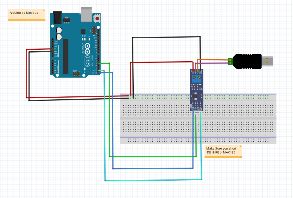
Circuit Connection between MAX-485 TTL to RS-485 converter module and Arduino UNO:
| Arduino UNO | MAX-485 TTL to RS-485 Converter Module |
| 0(RX) | RO |
| 1(TX) | DI |
| 4 | DE & RE |
| +5V | VCC |
| GND | GND |
Circuit Connection between MAX-485 TTL to RS-485 Module and USB to RS-485 converter:
| MAX-485 TTL to RS-485 Converter Module | USB to RS-485 Module Connected with PC |
| A | A |
| B | B |

Programming Arduino UNO for RS-485 MODBUS Slave
The Arduino UNO is configured as Modbus Slave. So the slave Arduino is controlled by the Master Modbus Software. The communication between the Arduino UNO and the Modbus Master Software is accomplished by using the RS-485 module. For connecting it with the PC, the USB to RS-485 converter module is used. And the Arduino UNO with MAX-485 TTL to RS-485 converter module, the whole setup will look file follows:
For using Modbus in Arduino UNO, a library <ModbusRtu.h> is used. This library is used for communicating with RS-485 Modbus Master or Slave via RTU protocol. Download the Modbus RTU.
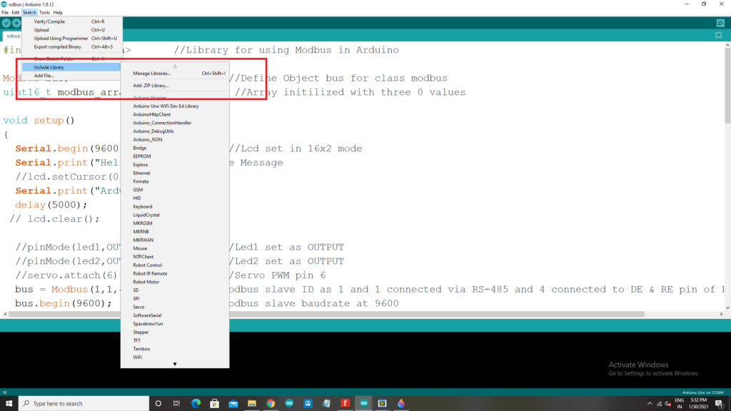
Add the library in the sketch by following Sketch->include library->Add .zip Library. Programming has some major steps which will be explained below.
- The Library we will be using here is ModbusRtu.h
#include<ModbusRtu.h> //Library for using Modbus in Arduino- Initialize bus object for class Modbus.
Modbus bus; //Define Object bus for class modbus - Next for storing values for Modbus communication an array is declared with the three values initialized with zero.
uint16_t modbus_array[] = {0,0,0}; //Array initialized with three 0 values- In the Setup function we will set the baud rate and will Print a welcome message on the serial monitor
Serial.begin(9600);         //Baud Rate
Serial.print("Hello"); //Welcome Message- Now for the Modbus communication, the following parameters are set. First ‘1’ represents Slave ID, second ‘1’ represents that it uses RS-485 to transfer data and ‘4’ represents RS-485 DE & RE pin connected to Arduino UNO.
//Modbus slave ID as 1 and 1 connected via RS-485 and 4 connected to DE & RE pin of RS-485
bus = Modbus(1,1,4); - The Modbus slave is set at 9600 baud rate.
bus.begin(9600); //Modbus slave baud rate at 9600- The loop starts with the definition of bus poll and bus.poll() is used to write and receive value from the master Modbus.
bus.poll(modbus_array,sizeof(modbus_array)/sizeof(modbus_array[0])); //Used to receive or write value from Master
This method is used to check if there is any data available at the serial port.
If there is any data available at serial port the Modbus RTU library will check the message (check the device address, data length, and CRC) and perform the required action.
For example, to write or read any value from the master, the Modbus RTU must receive an unsigned 16-bit integer array and its length from the Master Modbus. This array carries the data that is written from the master.
The next step will be testing it as Modbus Slave.
#include<ModbusRtu.h>       //Library for using Modbus in Arduino
Modbus bus;                          //Define Object bus for class modbus
uint16_t modbus_array[] = {0,0,0};    //Array initilized with three 0 values

void setup()
{
  Serial.begin(9600);                //Lcd set in 16x2 mode
  Serial.print("Hello");     //Welcome Message
  Serial.print("Arduino Slave");
  delay(5000);
  //Modbus slave ID as 1 and 1 connected via RS-485 and 4 connected to DE & RE pin of RS-485
  bus = Modbus(1,1,4);
  bus.begin(9600);                //Modbus slave baudrate at 9600
}

void loop()
{
 //The below statement is Used to receive or write value from Master
 bus.poll(modbus_array,sizeof(modbus_array)/sizeof(modbus_array[0]));
  if (modbus_array[0] == 0)//Depends upon value in modubus_array[0] written by Master Modbus
  {
    Serial.println("Data 1");   // Dummy Strings
  }
  else
  {
     Serial.print("NO Data 1");  // Dummy Strings
  }

 if (modbus_array[1] == 0) //Depends upon value in modbus_array[1] written by Master Modbus
  {
     Serial.println("Data 2");    // Dummy Strings
  }
  else
  {
     Serial.print(" NO Data 2");  // Dummy Strings
  }

  int pwm = modbus_array[2]; //Depends upon value in modbus_array[1] given by Master Modbus
  Serial.print("Mod bus:");
  Serial.println(pwm);
  delay(200);

}
Testing the Arduino UNO as Rs485 Modbus Slave
After the circuit connections are completed and the code is uploaded to the Arduino UNO, it’s time to connect the USB to RS-485 module with the PC where the Simple Modbus Master software is installed.
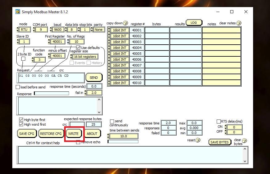
Open the device manager and check the COM port according to your PC where the USB to RS-485 Module is connected and after that open the Simply Modbus Master 8.1.2 software.
- After Simply Modbus Software is opened now open the Write option.

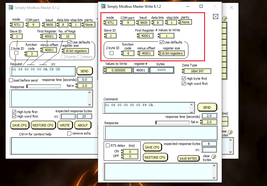
- After the Simply Modbus Master Write is opened. Set the parameters
Mode in RTU, COM port according to your PC , Baud at 9600, Data Bits 8, Stop bit 1, Parity None and Slave ID as 1.

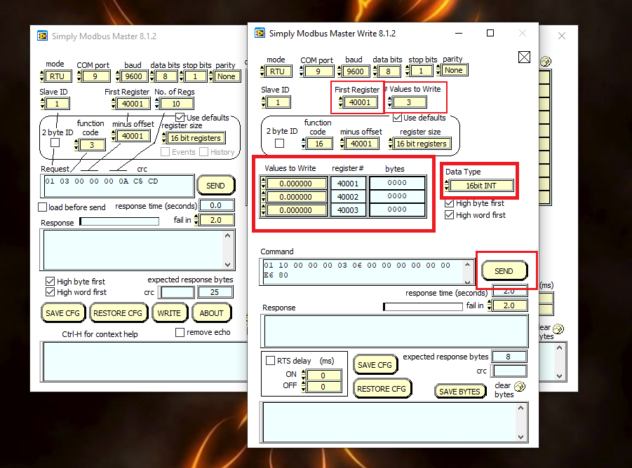
- After that set the first register as 40001 and values to write is 3 and the function code as 16 (Write Holding Register).
After that write 1 to 40001 for array1[ ] and 1 to 40002 for array2[ ] and write some random numbers to 40003 array3[ ] and then click SEND button.

- These steps are to confirm that the communication is happening between the devices.

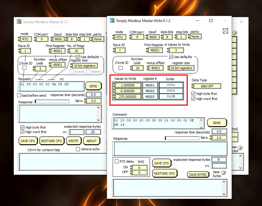
- Whatever values you type on the marked box and click on send, those values will be visible on the serial monitor of the Arduino IDE. That means communication is successful.
- Now, these are the steps used to write data using an Arduino as a slave, next we will use an Arduino as a master to read data.
Arduino as Master to Read Data
- Download the Modbus master library from the internet
- Once you download the library, add the .zip file
Go to→ Sketch→ Include Library→ Add .zip file

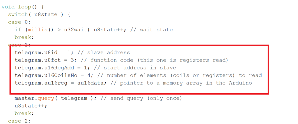
- Now go to examples in the IDE Examples→ Modbus Master slave for Arduino →Simple Master
- For Reading data we require another software called Serial Port Monitor
- Download and install the software.
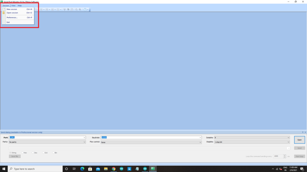
- Upload the code to the board, then open the serial port monitor
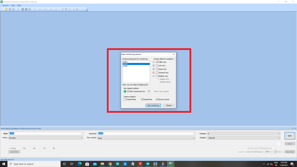
- Click on session → Start Session → Start Monitoring, then a pop window will appear.
- Now in the data box select your Arduino com port and click on start monitoring.
- At the bottom of the window, you can see COM port selection, select the com port of your Arduino with the appropriate baud rate. Click on Open,
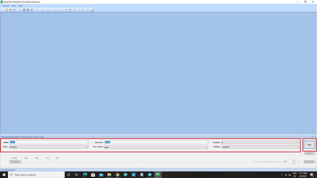
- Once you click on open, Data readings will be displayed on the screen
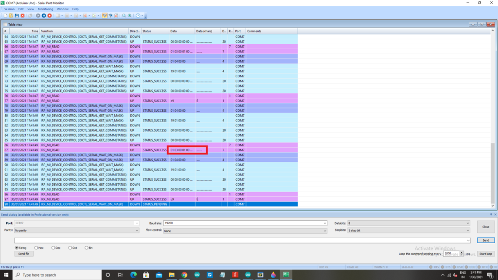
- The marked values which are displayed on the above image are the values taken from the program.

- The values can be changed here in the program, once the values are changed the program has to be reuploaded to the board and those new values can be viewed on the software.
All the components used in this article are readily available on our website. Please visit: PROBOTS to buy any components you need to kickstart your project.
hello sir,
i need to sense analog input of arduino and need to display it on modscan or simply modbus software on computer, actually i done the same thing by arduino as master. but the thing is i need to configure arduino as slave and need to read the analog input values and display it to master software. can you please help me sir.
Hey abhijith,
This article contains sections both on Arduino as slave and Arduino as master, please breeze through and follow the instructions given in the article.
feel free to contact us at info@probots.co.in
Thank you for this tutorial, I have a question please :
Can I combine the two Arduino codes in one code, because I want that the Arduino sends data to the computer and also reads data.
How can I do that ?
Thank you.
Not correctly. Both TX and RX are connected to RO.
Circuit Connection between MAX-485 TTL to RS-485 converter module and Arduino UNO:
Thanks your are correct. We have updated the article now. Thanks a lot!!
Hello Abhishek,
Thanks for the article. Is there any provision to access specific holding registers set at the master side?
Yes. Can be done.