Today in this article we are going to work with a sensor in the Microwave Radar Sensor series. The HFS-DC06 is a Microwave Radar Sensor that is designed for movement detection, like intruder alarms, occupancy modules, home automation, sea ice monitoring, biosensing, Robotics, smart factory, smart agriculture, and forestry, military equipment and other innovative ideas.

To know more about Microwave radar sensors we have a stand-alone article, please visit the link given, because here I will get directly into the product, and it’s working.
All the modules that you require to implement this project are available on our website. Visit Probots.
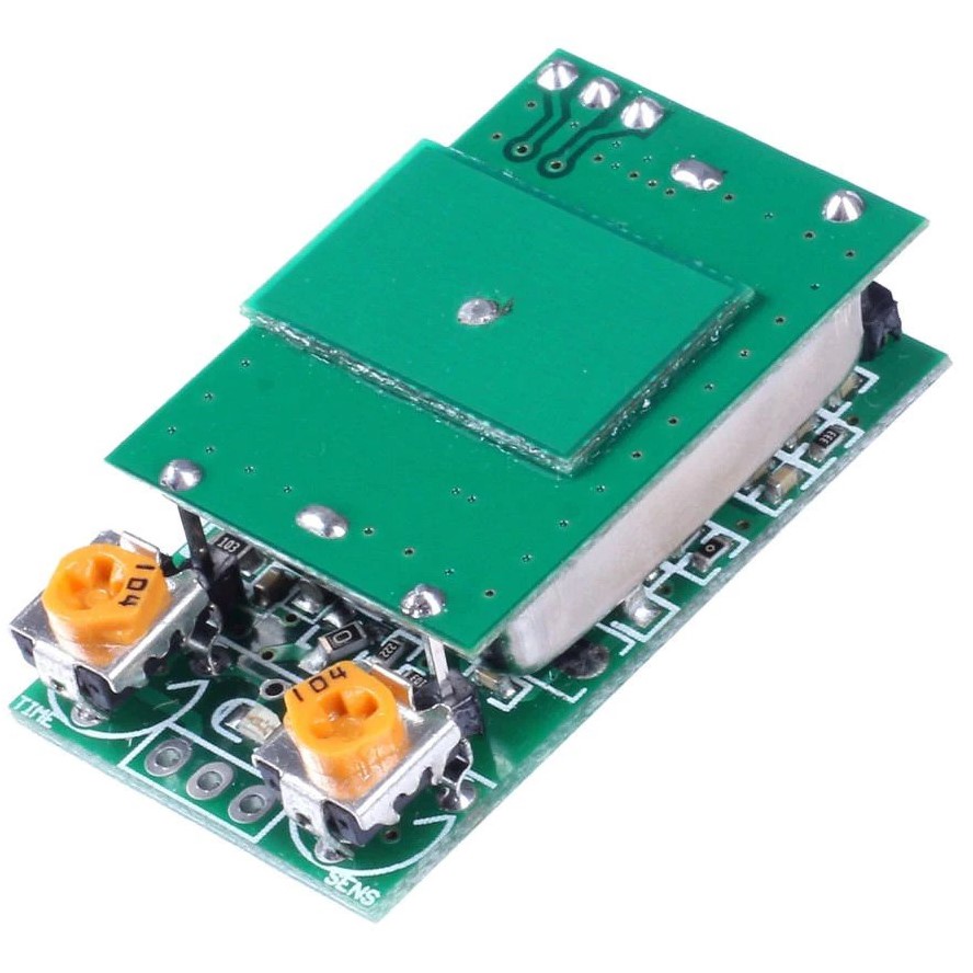
This module has a guaranteed sensing range of up to 4 meters, we have tested this sensor and found it working up to 20m having the right conditions. This sensor works on Stable 5V (input voltage). The user may vary the orientation of the module to get the best coverage. Similar to the HW-MS03 but it offers high accuracy and high range.
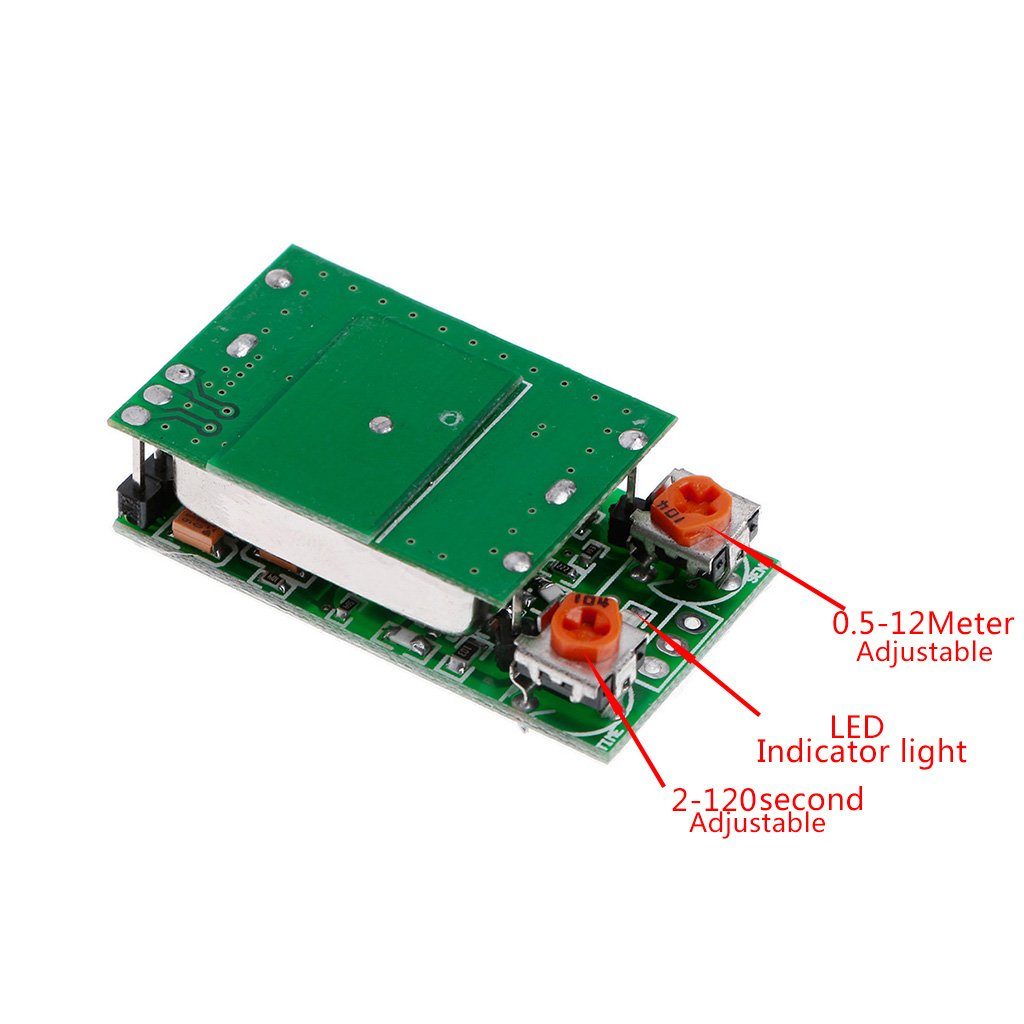
For sensitivity adjustment, 2 knob type pins are provided, one for range adjustment and one for motion detection time.
Turning the sensitivity Knob clockwise increases the range and turning the knob anti-clockwise decreases the range. Similarly turning the time knob would increase the time taken by the sensor to record the next reading.
NOTE:-
- For a stable 5V, we have used a 5V adapter, so there aren’t any fluctuations from incoming current or voltage
- The supply current must be greater than 30 mA to drive the module, if there are any high fluctuations, a continuous trigger is triggered (the charging lamp can continuously self-operated or not switch off)
- The product must not be installed near a large area of the metal body, it cannot be placed in a completely enclosed metal casing, which will affect the performance of this product or cannot be used normally.
Now to work with this microwave sensor, we need few components, once that is done we will move to the wiring diagram and the coding section.
Components Required:
Arduino
HFS – DC06 Microwave radar sensor
Jumper Wires
LED
Wiring Diagram:
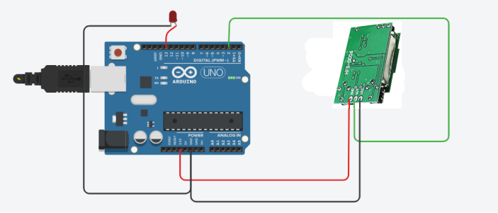
Pin Connections:
| Arduino | HFS - DC06 |
|---|---|
| Stable 5V | VCC |
| GND | GND |
| 2 | OUT |
Code:
/**
 * This code is written  to visualise the working of the microwave radar sensor
 * For more such interesting articles on products and their working visit: Probots
 *
 * @author  Abhishek S
 *
 */

#define inPin  2
#define Led_Pin 13
void setup()
{
   pinMode(inPin, INPUT);  // Initializing the declared inPin as INPUT
   pinMode(Led_Pin, OUTPUT); // Initializing the declared Led_Pin as OUTPUT
   Serial.begin(9600);
   Serial.println("HFS-DC06 Radar test");
}
void loop()
{
  bool reading = digitalRead(inPin);
  if (reading == HIGH)
  {
    Serial.println("MOVEMENT!");
    digitalWrite(Led_Pin, HIGH);
  }
  if (reading == LOW)
  {
     Serial.println("NO MOVEMENT!");
     digitalWrite(Led_Pin, LOW);
  }
     delay(500); // wait 0.5 second
}
Code Explanation:
This code is pretty straightforward, but still, let us get into the code details without wasting time. The Coding begins with defining the pin numbers for sensor input, Led_Pin.
#define inPin  2
#define Led_Pin 13
In the void setup() I will initialize respective pin numbers as input and output. I will then serially begin with the baud rate @ 9600 and print a message
pinMode(inPin, INPUT);        // Initializing the declared inPin as INPUT
pinMode(Led_Pin, OUTPUT); // Initializing the declared Led_Pin as OUTPUT
Serial.begin(9600);
Serial.println("HFS-DC06 Radar test");
In Void loop() the main execution will take place
Here I will digital read the input pin of the sensor and store it in a variable of type bool
bool reading = digitalRead(inPin);With the stored variable I will now put that variable in an if condition to detect the movement, ie. When the sensor is triggered, the pin becomes high and in turn prints the message and turns ON the LED
if (reading == HIGH)
{
   Serial.println("MOVEMENT!");
   digitalWrite( Led_Pin, HIGH);
}
Again using the stored variable I will put that variable in an if condition to detect movement, ie. When the sensor is not triggered, the pin becomes low and in turn prints the message and turns OFF the LED.
if (reading == LOW)
  {
     Serial.println("NO MOVEMENT!");
     digitalWrite(Led_Pin, LOW);
  }
     delay(500); // wait 0.5 second
}
Once you have made the connections and uploaded the code, the results will look something like the below images
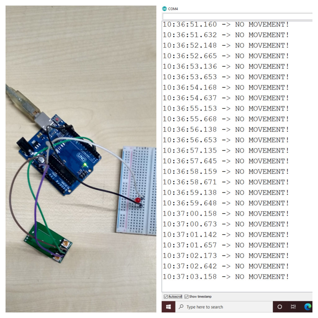
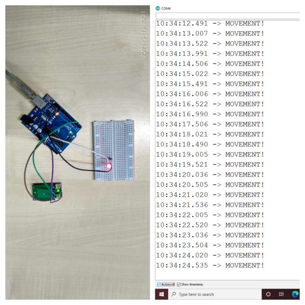
All the components used in this article are readily available on our website. Please visit: PROBOTS to buy any components you need to kickstart your project.
How to solve the false triggering issues of this sensor?
Hi Shibaditya,
There are 3 things you need to look into
1. Power Supply: You need to have a stable power supply(5V)(1A), connecting to USB won’t help.
For a stable 5V, you need to use a 5V adapter, so there aren’t any fluctuations from incoming current or voltage
2. Sensitivity: Adjust the sensitivity/Triggering time by turning the knob on the sensor.
when the sensitivity is too high even small movements or vibrations will trigger it.
3.Sensing Angle: This sensor senses at a certain angle, change the orientation of the sensor, and verify
Hello please let us know what data are published through the serial port ?
Any information such as amplitude , strength and distance can be obtained ?
Hai,
This sensor will not give you any information such as amplitude, strength and distance.
This motion sensor gives out only digital output. (ie. Movement(1) or No Movement(0))
Does anyone know of a small radar sensor that has the ability to give more feedback, such as amplitude and strength, signal loss, etc?
Hey Peter,
Please visit our online store for details on radar sensors.
You can try this – https://www.probots.co.in/radar-motion-sensor-cdm324.html
Is that sensor can penetrate the signal in wood?
or
which sensor is able to do this?
It can. But the range will be reduced.