
Optical liquid level sensors are solid-state liquid level sensors, meaning they have no moving parts to cause unreliability. They use infra-red light and can be used in environments where a traditional float switch would not be suitable to detect liquid levels.
All the modules that you require to implement this project are available on our website. Check Probots
Why to use an Optical Liquid Sensor?
The advantages of an optical liquid level sensor are their compact size, solid-state design, low cost, and reliability with extremely accurate point level sensing in high pressure, temperature, and at times corrosive environments. They are less useful for continuous level measurement applications. They are simple and easy to use with microcontrollers and general-purpose circuits.
Working Procedure:
Optical liquid level sensors do not measure the liquid level, instead, they detect the presence or absence of liquid directly in front of the sensor tip. Optical liquid level sensors consist of two parts; An Infrared LED and phototransistor that is accurately positioned at the base of the sensor tip.
When the sensor is not in contact with the liquid, infra-red light reflects internally around the tip of the phototransistor providing strong optical coupling between the two. When the sensor tip is immersed in liquid, the infra-red light escapes from the tip causing a reduction in the amount of light at the phototransistor which makes the output change state.
Product Specifications:
- Operating voltage: DC with suitable Resistors for the LED
- Output current: 12 mA
- Working temperature: – 25 ~ 105 ℃
- Low level output: < 0.1 V
- High level output: > 4.6 V
- Life: 50,000 hours
Pin Description:
| Pin No | Colour | Description |
| 1 | Red | Sensor GND |
| 2 | Yellow | Sensor GND |
| 3 | Blue | IR LED VCC |
| 4 | White | Phototransistor VCC |
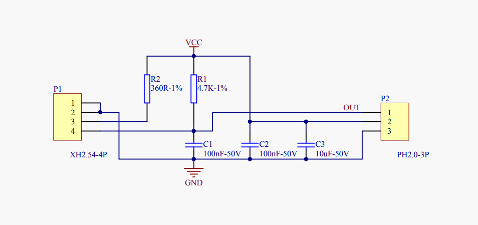
Circuit Diagram:

Sensor Working
- Use the above circuit to connect the sensor to your microcontroller.
- P1 is the 4 Pin connector coming out from the sensor
- P2 is the connection to your Arduino, ESP32, NodeMCU, any other microcontroller.
- VCC can be 5V for this circuit.
- R2 is the current limiting resistor for the internal IR LED. Value can be between 180 Ohm to 1K Ohm
- R1 is the resistor divider for the phototransistor. Value can be between 4.7K to 10K.
- Capacitors C1, C2, and C3 are optional and for power filtering. Can be used if the power supply is noisy.
- The OUT line gives an analog voltage depending on the liquid level.
- OUT is 0V when no liquid, and 5V when liquid is detected.
Sample Arduino Code:
Upload the below code to the arduino and open the serial monitor, set the baud rate to 9600 as given below.
int OpticalSensorPin = 0; // Connect signal pin to A0
int OpticalSensorReading; // variable to hold the optical float sensor
void setup(void)
{
  Serial.begin(9600);
}
void loop (void)
{
 OpticalSensorReading = analogRead(OpticalSensorPin);// take a reading from the sensor  pin
 Serial.print("OPTICAL SENSOR READING = ");
 Serial.print(OpticalSensorReading); // the analog reading of the optical sensor
 if (OpticalSensorReading > 900)
 {
   Serial.println("  LIQUID DETECTED ");
 }
 else
 {
   Serial.println(" NO LIQUID");
 }
}
Output

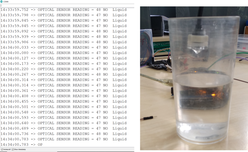
Before dipping the optical sensor into the liquid

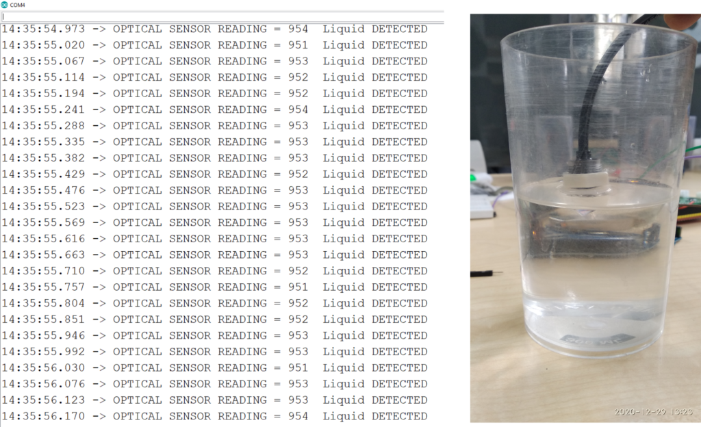
After the optical sensor comes in contact with the liquid
Applications:
- Water dispenser
- Humidifier
- Water tank
- Electrical appliances requiring liquid level detection etc.
All the components used in this article are readily available on our website. Please visit: PROBOTS to buy any components you need to kickstart your project.