
In this article, we will try to understand how to interface the MAX30102 sensor with the ESP32 microcontroller and publish values onto the AWS IoT cloud.
Materials required:
- ESP32 Dev module
- MAX30102 breakout board
- Jumper wires
- ESP32 boards add-on Arduino IDE
We’ll program the ESP32 using Arduino IDE. So, you must have the ESP32 add-on installed. Follow the next tutorial if you haven’t already: Installing ESP32 Board in Arduino IDE (Windows, Mac OS X, Linux).

- MAX30102 Pulse oximeter
The MAX30102 sensor is an integrated pulse oximeter and a heart-rate monitor module. It includes internal LEDs, photodetectors, optical elements, and low-noise electronics with ambient light rejection. The MAX30102 provides a complete system solution to ease the design-in process for mobile and wearable devices.
The MAX30102 operates on a single 1.8V power supply and a separate 3.3V power supply for the internal LEDs. Communication is through a standard I2C-compatible interface. The module can be shut down through software with zero standby current, allowing the power rails to remain powered at all times.
Application: wearables, fitness monitors, phones, tablets.
Connections:

- Libraries
We need to install it on Arduino externally or on manage libraries under the sketch tab in the menu bar.
- MAX30102: GitHub or we can go search Sparkfun MAX3010X Arduino library manager.
- AWS IoT: there is the official documentation from the AWS website esp32 board with AWS IoT which you can refer to the link. In this particular project, we have a slightly different approach to implementing it, we have to download this library for the same: link.
- AWS setting up
- First, we need to log in to the AWS console and go to AWS IoT. On the left panel of the dashboard, we view multiple options, from which we need to navigate to Manage> Create things.

- Once we click on to create things there is an option to create a single thing and create many things.
- For this application, we go create a single thing and provide it with a name, for example, spo2 and for the shadow option, it should be no shadow.
- Once this is created, we go to the device certificate where we select the option Auto-generate a new certificate.
- We then come across the across create a policy under any respective title, in our case, it was policy_max30102, and type in the asterisk into both the action and ARN box which you find below.

- Once the policy is created, we attach the policy to the thing we created and we download the device certificate, primary key, and root CA key.
- We need to name a shadow to get the MQTT protocol to copy to the Arduino code.
- Once this is done, we need to go to the AWS IOT folder in Arduino libraries> AWS IOT> SRC> CERTIFICATES. In the certificate, we need to paste the downloaded keys into their respective heading with each line ending with ‘\n\’.
- Now we can go back to the Arduino code:
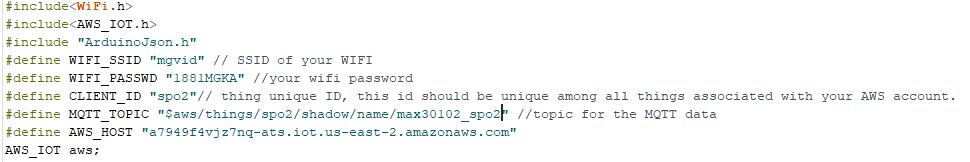
- Here we assign the WIFI SSID AND PASSWORD of the network in use. For client ID which is ‘spo2’ and MQTT topic which you get in device shadows and AWS HOST which you need to visit the setting options, scroll near to the end to find it.
- The code will be uploaded on the GitHub profile.
- Working/Demonstration
We can view what will be displayed on the serial Monitor and what is displayed on the AWS IOT console. To access the value you need to visit the test icon on the left panel of the dashboard. We will see the option device gateway where we have to paste the MQTT topic and we have access to the values coming from the sensor.
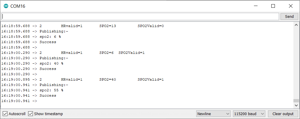
Serial monitor output
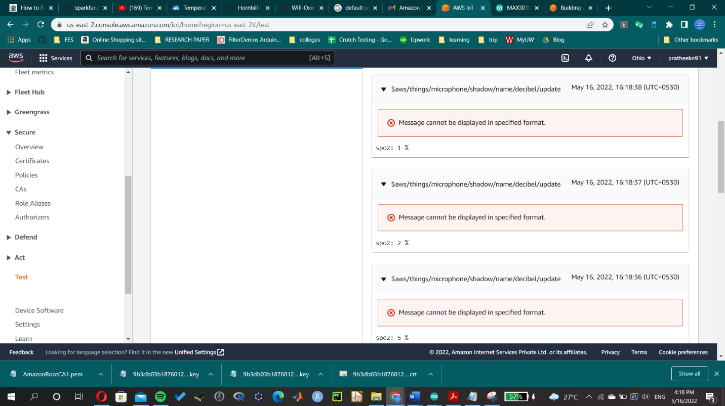
AWS DASHBOARD VIEW