
As ultrasonic sensors started being used in cars as reverse parking sensors, manufactures started producing them in bulk which made them easily available in a wide variety of models at cheap prices. We at Probots (www.probots.co.in), sell a wide range of ultrasonic sensors which are easy and simple to interface with microcontrollers.
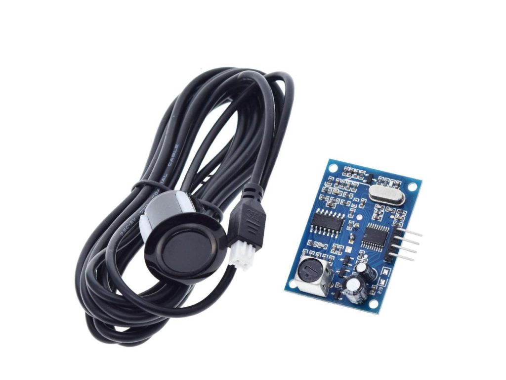
The most versatile and accurate of them is the Waterproof Ultrasonic Sensor AJ-SR04M/JSN-SR04T V2.0. It can detect objects up to 4.5meters, has a very practically useful beam angle of 45 degrees, is accurate up to 0.5cm. Unlike other ultrasonic sensors HC-SR04, JSN-SR04T, and the JSN-SR04T V2, the AJ-SR04M offers a wide range of operating voltage 3-5V(which means it can work on both 5V and 3.3V microcontrollers), has a low power consumption of only 20uA during sleep(which means it can run on batteries for years!). The other sensors HCSR05 and JSN-SR04T have high operating voltage and current consumption( which makes the AJ-SR04M is the best choice for designing consumer products).
Make sure you buy only genuine sensors which come fully functionally tested. Many fakes, clones, and low-cost modules may not give you these options and you may be unable to get them working following this guide.
Check out our website www.probots.co.in to find all the parts for your projects! We have 2000+ Electronic Modules, Sensors, and Components for all your electronics projects.

You can purchase this signal generator here – Buy Now
The sensor has multiple operating modes –
- Traditional Trigger and Echo Mode
- Low Power Traditional Trigger and Echo Mode
- Automatic Serial Port Mode
- PWM Output
There are many articles and YouTube videos showing that JSN-SR04T V2 and AJ-SR04M are not working and they recommend using SN-SR04T. But they didn’t put in an effort to get them working but just concluded that an older sensor JSN-SR04T with fewer features is better.
We recently delivered a custom electronics product using the AJ-SR04M and were able to get it working with no issues. The product has already reached the market and has been received with high satisfaction from both our customers and their users.
If you are trying to use this ultrasonic sensor in your product or project, then this article will help you get it working immediately. We sell the same sensor on our website – Buy Now on www.probots.co.in
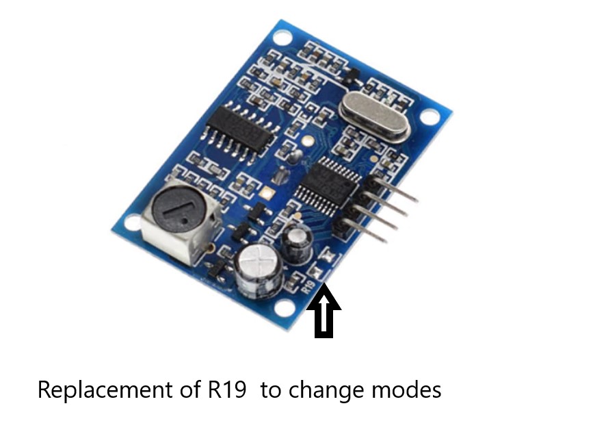
Modes Selection:
Specification:
- Operating Voltage: DC 5V
- The Module is has an operating range of 20cm to 450cm.
- Total Current Draw:30mA
- Frequency: 40KHZ
- Resolution : about 0.5cm
- Beam Angle: less than 50 degrees
- Working Temperature:-10~70° C
- Storage temperature:-20~80° C
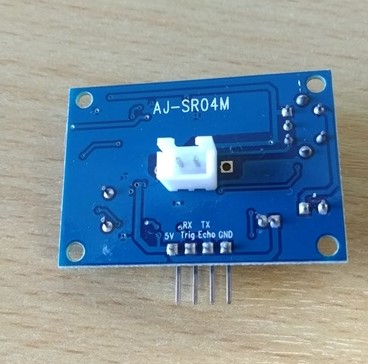
Board Overview :
The AJ-SR04M has 5 working modes:
- Traditional Trigger and Echo Mode (same as the popular HCSR04):
This mode uses Trigger and Echo pins. You will have to allocate two digital pins on your microcontroller, and a software timer to calculate the distance.
Note that the communication sequence is the same as per HC SR04, but make sure your high signal on the Trigger pin is at least 10 ms wide. Some users have reported getting good reading only after increasing the trigger width to 20m.
This mode works with the popular Arduino Newping Library. to use this sensor with NewPing Library, (not necessary to use this library in, you can also get the sensor working with a few lines of code. Library makes it simple though )
Sample Code to test Echo Trigger Mode –
#define echoPin 11 // attach pin D2 Arduino to pin Echo of JSN-SR04T
#define trigPin 12 //attach pin D3 Arduino to pin Trig of JSN-SR04T

// defines variables
long duration; // variable for the duration of sound wave travel
int distance; // variable for the distance measurement

void setup() {
  pinMode(trigPin, OUTPUT); // Sets the trigPin as an OUTPUT
  pinMode(echoPin, INPUT); // Sets the echoPin as an INPUT
  Serial.begin(9600); // // Serial Communication is starting with 9600 of baud rate speed
  Serial.println("Ultrasonic Sensor HC-SR04 Test"); // print some text in Serial Monitor
  Serial.println("with Arduino UNO R3");
}
void loop() {
  // Clears the trigPin condition
  digitalWrite(trigPin, LOW);  //
  delayMicroseconds(2);
  // Sets the trigPin HIGH (ACTIVE) for 10 microseconds
  digitalWrite(trigPin, HIGH);
  delayMicroseconds(10);
  digitalWrite(trigPin, LOW);
  // Reads the echoPin, returns the sound wave travel time in microseconds
  duration = pulseIn(echoPin, HIGH);
  // Calculating the distance
  distance = duration * 0.034 / 2; // Speed of sound wave divided by 2 (go and back)
  // Displays the distance on the Serial Monitor
  Serial.print("Distance: ");
  Serial.print(distance);
  Serial.println(" cm");// working  code for aj-sr04m
}This mode is useful if you want to replace a traditional trigger/echo sensor with this module. Numerous libraries are available so programming is easy. But it requires 2 IO Pins and gets complicated as the number of sensors increase.
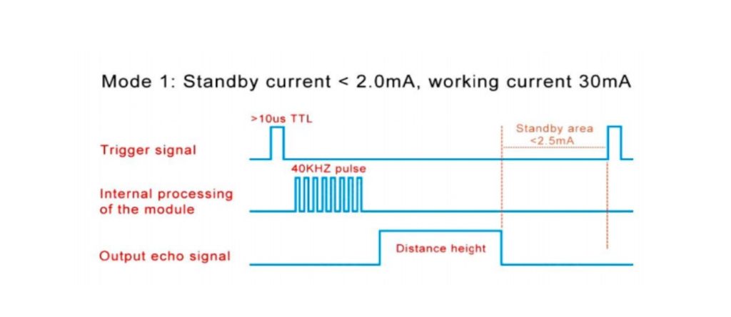
- Low Power Traditional Trigger and Echo Mode
This Mode of working is similar to the previous mode, but it offers extreme low power consumption. This mode consumes only around 40uA of current during sleep. Perfect if you are powering the sensor from a battery. To enter this mode replace resistor R19 by 300KΩ resistor onboard.
In this mode, the module is in sleep mode, when a high signal with a pulse width of more than 1ms TTL trigger is supplied, the module starts transmitting and receiving the ultrasonic signal.
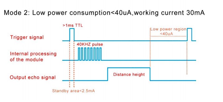
The working code for his mode is the same as mode 1. Modify the trigger pulse to a pulse width greater than 1ms to trigger the sensor from sleep mode.
This Mode is very useful if you use the sensor in low-power battery-driven applications. It offers low power consumption, zero interference with other sensors, and is simple to use.
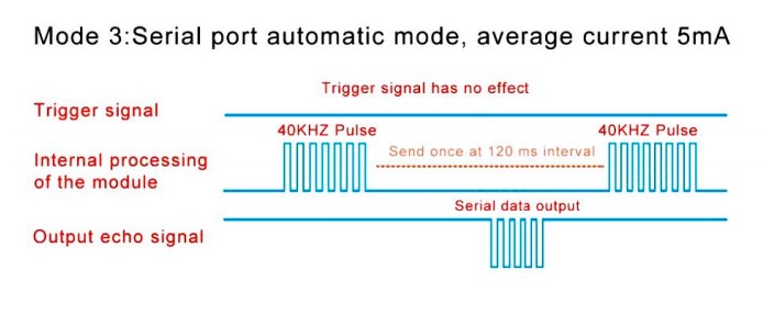
- Automatic Serial Mode
Use Resistance value 120KΩ, to enter the Automatic Serial port mode. The trigger signal is not used in this mode. In this mode, the distance calculation happen on the sensor and it outputs the distance directly over the Echo line every 120ms.
AJ-SR04m transmits bytes per measurement, which is shown below.
| Byte1 | Byte2 | Byte3 | Byte4 |
|---|---|---|---|
| Start Byte | Upper Byte | Lower Byte | Checksum |
40KHZ pulse generated internally for every 120ms and gives the output distance in echo line. distance in (mm). The checksum is the output, and it is the sum of the Upperbyte and LowerByte. Checksum is used to verify the packet loss during transmission.
Sample Code to test Automatic Serial Mode –
#include <SoftwareSerial.h>
#define rxPin 10
#define txPin 11

SoftwareSerial jsnSerial(rxPin, txPin);

void setup() {
  jsnSerial.begin(9600);
  Serial.begin(9600);
}

void loop() {
  /*jsnSerial.write(0x01);
   delay(10);*/
  if(jsnSerial.available()){
    getDistance();
   //

  }

}
void getDistance(){
  unsigned int distance;
  byte startByte, h_data, l_data, sum = 0;
  byte buf[3];

  startByte = (byte)jsnSerial.read();
  if(startByte ==255){
    jsnSerial.readBytes(buf, 3);
    h_data = buf[0];
    l_data = buf[1];
    sum = buf[2];
    distance = (h_data<<8) + l_data;
    if((( h_data + l_data)) != sum){
      Serial.println("Invalid result");
    }
    else{
      Serial.print("Distance [mm]: ");
      Serial.println(distance);

    }
  }

  else return;
  delay(100);
}
Use this mode if you do not want to do the distance calculations on your host microcontroller.
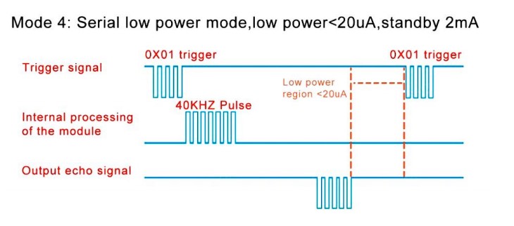
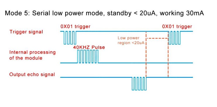
- Low Power Serial Mode:
Use 47KΩ at R19 to enter the Low power Serial Mode. In this mode the sensor is in low power sleep mode and consumes 20uA. When the trigger command(0x01) is received on the trigger pin, the sensor wakes up, performs distance calculation and outputs the distance over the echo line. The sensor goes back to sleep after transmitting data. This mode has a low power consumption compared to the previous mode 3.
Sample Code to test Low Power Serial Mode –
#include <SoftwareSerial.h>
#define rxPin 10
#define txPin 11

SoftwareSerial jsnSerial(rxPin, txPin);

void setup() {
  jsnSerial.begin(9600);
  Serial.begin(9600);
}

void loop() {
    jsnSerial.write(0x01);
    delay(50);
  if(jsnSerial.available()){
    getDistance();
  }
}
void getDistance(){
  unsigned int distance;
  byte startByte, h_data, l_data, sum = 0;
  byte buf[3];

  startByte = (byte)jsnSerial.read();
  if(startByte == 255){
    jsnSerial.readBytes(buf, 3);
    h_data = buf[0];
    l_data = buf[1];
    sum = buf[2];
    distance = (h_data<<8) + l_data;
    if((( h_data + l_data)&0xFF) != sum){
      Serial.println("Invalid result");
    }
    else{
      Serial.print("Distance [mm]: ");
      Serial.println(distance);
    }
  }
  else return;
}Use this mode if you do not want to do distance calculations on your host and if you want low power applications.
- Computer Printing Mode:
Simply short the resistor R19(0 Ohm) to enter to this mode. This is the easiest mode compare to other modes – the distance calculation happens onboard and the output data is directly readable on any serial terminal software(including the Serial Monitor on Arduino IDE).
Sample Code to test Computer Printing Mode –
#include <SoftwareSerial.h>
#define rxPin 10
#define txPin 11

SoftwareSerial jsnSerial(rxPin, txPin);

void setup() {

  jsnSerial.begin(9600);
  Serial.begin(9600);
}

void loop() {
    jsnSerial.write(0x01);
    delay(10);
    if(jsnSerial.available()){
    Serial.println(jsnSerial.readString());
  }
}Use this mode if you want a quick and easy way to read the sensor data. Without any host processing.
You can purchase all products that were used in this article here –
- Ultrasonic sensor,
- Arduino Uno
- Breadboard
- Jumper Cables
Many such modules are available for sale on our website. You can check them out here – www.probots.co.in
Many thanks! very complete guide!
Would you please teach me how to connect the AJ-SR04M to a ESP32 DEVKITV1?
Thank You
Follow the same steps. Change IO pins in program and circuit to match the ESP32.
You can follow the same tutorial. Just change the IO pins to suitable pins on the ESP32
Excelent….complete guide!
Would you please teach me how to connect the AJ-SR04M to a ESP32 DEVKITV1?
Thank You
Follow the same steps. Change IO pins in program and circuit to match the ESP32.
You have 3 different pictures of the module. Which is current
You are right. These are generic modules and keep changing. Unfortunately we dont have any any fixed reliable version/identification yet.
We rely on the model number that is printed on the PCB. The latest one are marked AJ-SR04M V2.
it can compatible with the raspberry pi ?
Sure. Libraries are available or you can write the code on your own too.
Heya i am for the first time here. I came across this board
and I find It really useful & it helped me out a lot.
Hi,
I have the previous version of the sensor SR04M-2. Can I connect the sensor to NodeMCU? If yes, how, and if not why? I highly appreciate your answer.
Thanks!
Kind regards,
Sanjeev
You can use it with NodeMCU. Don’t see why you cannot it is a very simple digital interface.
Make sure you connect VCC of the sensor to 5V on the NodeMCU.